

Home » Guides » Cases & Brands »
Building a Rack: Planning, Power, Ventilation and Cable Management
How to plan a 19 inch rack before you buy it: what goes where and why, powering it from one inlet, keeping it cool, and cable management you can service.
~8 min read · Updated July 2026 · By the Stage Supply team
In this guide: Planning · Units and depth · Power · Ventilation · Cable management · Shock mounting · Accessories · Worked examples · Testing · Mistakes · FAQ
Plan it on paper before you buy anything
A rack is a plan before it is a purchase. Ten minutes with a pencil finds the depth problem, the missing rack units and the nowhere-for-the-cables-to-land problem. The workshop floor finds them at nine on a Thursday with the van booked for six.
Draw one column and number the rack units from the bottom up. Write each device in at its real height, so a 2U amplifier occupies two boxes, and note its depth, the face you touch, and where its cables go. Then order it by four rules.
- Heavy items low. Amplifiers and anything with a large power supply go at the bottom. A rack with its mass high up is unstable on castors and easy to tip going up a ramp. Get help lifting, and work inside the case manufacturer’s load rating.
- Things you touch at working height. Switches you use mid-show, receivers whose meters you read, the drawer you open in the dark, the patch field you repatch between acts.
- Patch panels where the cables land. Put connector panels on the face the loom arrives from, at the height it reaches. A panel at the top when the multicore comes in low leaves every cable under tension.
- Leave spare U. Two spare units feels wasteful until you add a receiver and every device you own is one U bigger than the gap. Spare U is thermal headroom too, so plan the rack you want and buy the next size up.
Rack units and depth, briefly
The 19 inch rack is standardised as EIA-310: a 19 inch (482.6 mm) panel width and one rack unit of 1.75 inches (44.45 mm), with the familiar unevenly spaced group of three mounting holes. The U counting maths and the shallow versus deep case decision are in the flight cases and racks guide. Two points wreck more builds than anything else.
Measure depth including connectors and the cable behind them. Manufacturers publish chassis depth: QSC list the CX-Q series as 2RU and 381 mm (15 in) deep, which is the box, not the box plus connectors and cable bend radius. Check your total against the usable internal depth of the case.
Deep, heavy devices may want fixing at the back too. QSC specify eight screws for the CX-Q, four front and four back. Not every case offers rear rails and not every device has rear ears, so check both.
Power inside the rack
The goal is that the finished rack has one thing to plug in: one inlet on the rear panel, one internal distribution unit, every device fed from it. That removes trailing sockets inside the case and half the rack on a different supply.
A rack PDU is a 1U or 2U panel with one input and a row of fixed outlets, bolted to the rails like any other device, available with UK 13A outlets, powerCON or powerCON TRUE1, IEC, C-Form inlets or Schuko. The features that earn their keep are individually switched outlets and power monitoring; our power distribution range covers them and the distribution boxes that feed them. A domestic trailing socket cable-tied to the frame has outlets not made for repeated insertion, no strain relief and no mechanical fixing.
Bring up sources and processing before amplifiers, and shut the amplifiers down first. A switched PDU makes that a row of switches you work left to right, so label them; the amplifier side is in our guide to matching amplifiers and speakers.
Keep mains and audio apart where the geometry allows. You rarely get real separation inside a rack, but you always choose which side a cable runs down. Take mains down one vertical run and audio and data down the other, cross them at right angles rather than side by side, and never bundle a mains tail and a microphone line into the same tie. How balanced lines reject noise is in our pro audio connectors guide.
Electrical work is for a competent person
Making off a mains inlet, wiring a distribution panel, altering a PDU or modifying any mains equipment is electrical work, and in the UK that is work for a competent person. Anything opened or modified should be inspected and tested before it goes back into service. Nothing here is electrical design guidance, and never lift or defeat an earth connection to cure a hum: it is dangerous, and it is not the fix.
Heat and ventilation
Amplifiers dump heat, and so to a lesser degree do DSP units, network switches and any sizeable power supply. Put several in a box with a lid on each end and you have built an oven.
Airflow direction is not universal, so read the manuals
There is no single convention. QSC specify the CX-Q series with side and rear to front airflow, so the exhaust leaves the front panel, while plenty of other amplifiers draw in at the front. Two units blowing in opposite directions in one rack is a real failure mode, because one breathes the other’s exhaust. The published clearances are non-negotiable: QSC ask that nothing blocks the front or rear ventilation openings and that each side has at least 2 cm clearance, and some manuals ask for spare units above and below stacks.
Poor ventilation makes the amplifier quieter, not dead
QSC state that insufficient ventilation may result in the amplifier reducing output power during normal operation, with the limiter and protect indicators lighting, so the PA is quieter in the second half than in soundcheck. Their ambient limits are lower than most people assume: 0 to 35°C recommended for the CX-Q, and reduced output stated above 35°C on the SPA-Qf series. The rack makes it worse, because in a closed or multi-unit rack assembly, as QSC put it, the ambient temperature of the rack environment may be greater than room ambient.
A sealed rack cooks its contents, and an empty U leaks
With both lids on and no vents, the air the equipment draws in is the air it just exhausted, a few degrees hotter each time round. Run with the lids off the faces that need to breathe, or fit a mesh or vented door.
An empty rack unit, meanwhile, is not a vent but a leak: cool air takes the easy route through the gap instead of through your equipment, and hot exhaust loops back to the intakes. Data centre practice is unambiguous that blanking unused units suppresses both. So blank the gaps you want air to go past, and vent the gaps you want air to go through. Vented panels, such as those in our racks and wall plates range, belong at the top of the rack or above a hot block of amplifiers.
Fan panels, thermostats and filters
Where passive airflow is not enough a 1U fan tray moves air on purpose, and thermostatic control keeps it quiet enough for a room you are mixing in. Penn Elcom’s FT-DTC is a 1U digital thermostatic controller built for this: a plug-in PTC sensor on a 1 m lead, a fan run indicator, an over temperature alarm and a switched 12 V DC output rated to 4 A. Filters keep dust and haze off the heatsinks but are a maintenance commitment, so put cleaning on the same schedule as the cable inspection in our cable care guide.
Cable management you can actually service
Service loops
Every cable at the back of the rack needs enough slack to slide its device forward far enough to reach behind it with everything still connected. Without that you have a rack you can dismantle, not one you can service. Allow the device to travel its own depth plus a margin, dress the loop to a vertical run so it cannot sag into a fan, then pull every device forward once: whatever tightens first is the loop you got wrong.
Cable ties, hook-and-loop, and labels
Nylon ties are permanent, and over-tightening deforms cable, which matters most on data cable where the geometry of the pairs is what makes it work. Use ties only where nothing will change, and hook-and-loop straps for everything you will ever change, which inside a rack is nearly everything. Both are in our cable ties and straps section. If the fixing marks the jacket it is too tight. Label both ends of every cable and the socket it belongs in, with cable markers or printed labels rather than marker pen on gaffer, which peels inside a warm rack; the methods that survive real use are in our guide to looking after your cables.
Patch panels take the wear so your equipment does not
Anything a human plugs into during a show should terminate on a panel on the rack face, not on the socket of the device: the panel is a consumable, the socket on the back of your mixer is not. Our racks and wall plates range includes punched panels in 2U and 3U with D-series and Neutrik cut-outs, plus punched power panels with 16A cut-outs. Use the panel-mount XLR version rather than adapting a cable connector.
Strain relief at the rear
Every cable leaving the rack should be anchored to the frame or a cable entry plate before it exits, so a pull outside becomes a pull on the frame rather than on a connector. Keep runs off the airflow paths while you are back there.
Shock mounting, and when it earns its cost
A shock-mount rack suspends an inner frame inside the outer case on elastomer or foam mounts, so impacts into the case are absorbed before they reach the equipment. It costs weight, internal depth and sometimes rack units; the construction detail is in the flight cases and racks guide.
Worth it when the rack goes in and out of a vehicle week after week, when it holds anything with a delicate mechanism, when it holds equipment you could not replace on a Saturday morning, and when other people handle it. Not worth it when the rack lives in a cupboard and moves twice a year. Either way, shock mounts eat internal depth, so measure your deepest device against the inner frame.
Rack accessories that pay for themselves
- Blanking and vented panels. Cheap, and they control where the air goes. Buy them with the case.
- Rack drawers and shelves, so adaptors, batteries and torch stop living in a carrier bag, and half-rack units get a proper home.
- Cable entry and gland plates, a proper exit for looms that permanently leave the rack, with strain relief designed in.
- Clip nuts and rack screws. Buy the pack of fifty. Nothing halts a build faster than being three M6 clip nuts short at nine at night.
- Rack sleeves wooden 19 inch sleeves from 2U to 10U, for studio, install and DJ use where you want a rack of equipment without a flight case.
- Tour labels, castors and catches. Spares of the flight case components you break turn a dead rack into a ten minute repair.
Two worked examples
A small front of house rack, 8U on castors
- U1: 1U rack PDU, individually switched, fed from a single rear inlet, near where the mains cable enters and switched left to right in power-up order.
- U2: 1U rack drawer for adaptors, batteries, torch and gaffer.
- U3 to U4: 2U punched patch panel carrying every connection the outside world plugs into. Working height, labelled, and it takes all the plugging wear.
- U5 to U6: 2U of wireless receivers, or a shelf carrying two half-rack units, at the height you read the meters.
- U7: 1U spare, blanked. Where the next thing you buy goes.
- U8: 1U vented panel, letting warm air out of the highest point.
At the rear: the loom lands on the patch panel, anchored to a cable entry plate; mains down one side and audio down the other; a service loop on every device.
An amplifier rack, 12U on castors
- U1 to U2: amplifier one. Heaviest device, lowest position.
- U3 to U4: amplifier two.
- U5 to U6: amplifier three, or the sub amplifier.
- U7: vented panel separating the hot block from everything above. If the manuals ask for spare units between stacks, that spacing goes inside the block too.
- U8 to U9: 2U rack PDU with power monitoring, at readable height.
- U10: 1U loudspeaker processor, sitting above the amplifiers because the weight rule forces that, with the vented panel below it.
- U11: 1U spare, blanked.
- U12: 1U thermostatically controlled fan panel drawing warm air out of the top.
At the rear: a vented door rather than a solid lid, nothing routed across an amplifier intake, loudspeaker outputs on a rear connector panel.
Testing before it ships, and the pre-show check
A rack is a product you have manufactured. Test it in the workshop, where a fault is an inconvenience rather than a disaster.
- Unplug and replug every connection once, to find the one that was only ever half mated.
- Power up in the intended order and confirm every switched way matches its label.
- Pass signal through every path on the patch panel, one at a time. A patch field with one crossed pair is worse than none, because you will trust it.
- Pull every device fully forward, still connected, and fix anything that tightens or fouls.
- Run it warm at a realistic level, lids as they will be in use, then feel the exhaust and the top of the case. Uncomfortable to touch is a ventilation problem.
- Photograph the front and rear and tape a print inside the lid.
- Check the mechanics. Castors roll, brakes hold, catches latch, lids seat.
On site, before doors: lids off the faces that need to breathe; filters clear and nothing stacked on a top vent; PDU switches in the state you expect; and a sweep of the rear for anything pulled tight or lying across an intake.
Common mistakes
- No spare U, so the rack is full the day it is finished and every future purchase is a rebuild.
- Everything jammed in with no airflow. Density is not the goal, and the published clearances are cheap to honour.
- Running sealed, so the equipment breathes its own exhaust and quietly derates.
- No labels, or labels on one end only, which is the same thing at two in the morning.
- No service loop, so nothing can be diagnosed without taking the rack apart.
- Mains and microphone lines tied into one bundle. Bad for noise, and every change means cutting into both.
- The heavy amplifier at the top. Unstable, and eventually somebody tips it over a threshold.
- Patching into the equipment’s own sockets, which makes the device the consumable instead of the panel.
- Guessing the depth. Chassis depth is not device depth, and internal is not external.
Popular picks from the shop
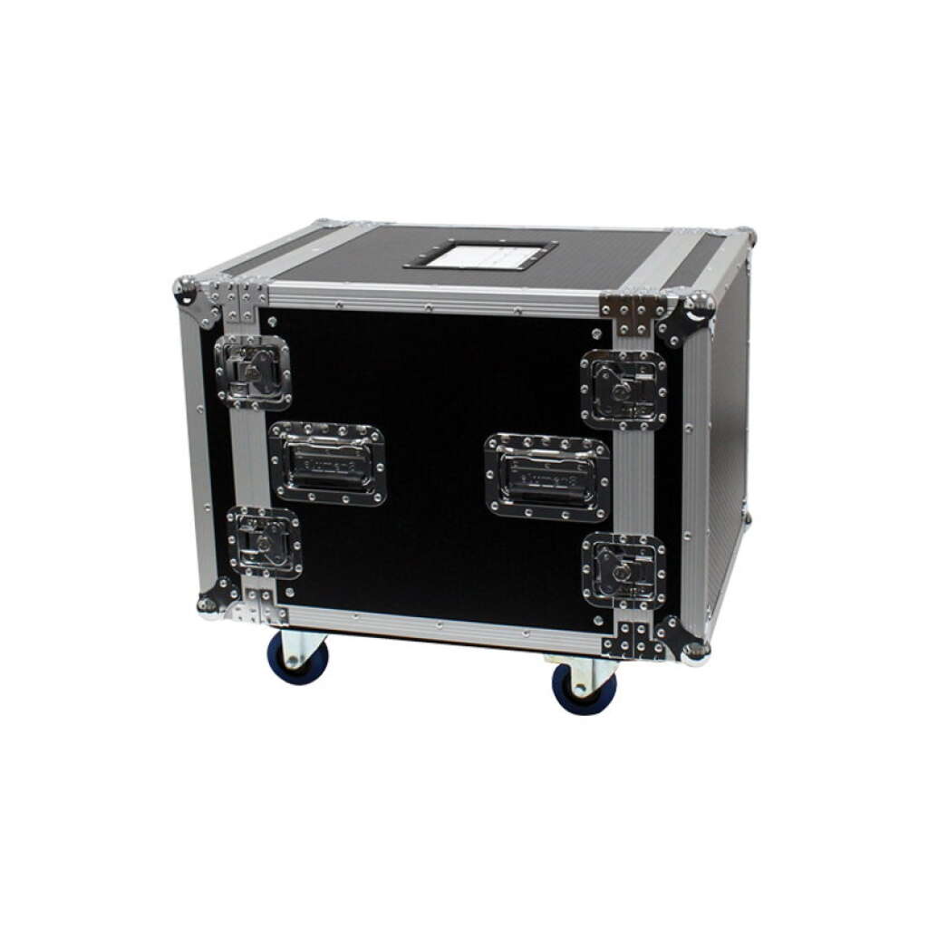
Elumen8 10U Rack Flight Case with WheelsView product → Penn Elcom 2U 19″ Vented Rack Panel (R1286/2UVK)View product → Penn Elcom PDU16-UKTR1 2U Rack PDU, 8 x 13A, powerCON TRUE1View product → Elumen8 Hook and Loop Cable Strap 25 x 245mm, Pack of 10View product →
Frequently asked questions
How do I build a 19 inch rack?
Plan it on paper first. Draw a numbered column of rack units from the bottom up, place each device at its real U height with its depth noted, put heavy items at the bottom, whatever you operate at working height, and patch panels where the cables arrive. Then power it from one inlet through a rack PDU, sort the airflow with vented and blanking panels, and give every cable a service loop.
What should go at the bottom of a rack?
The heaviest items, which normally means the amplifiers and anything with a large power supply. A rack with its mass high up is unstable on castors and unpleasant to move. Get help lifting, and stay inside the case manufacturer’s load rating.
Do blanking panels help or hurt rack cooling?
They help. An open rack unit lets cool air bypass your equipment and hot exhaust recirculate to the intakes, so blanking unused units forces air through the gear instead of round it. Use vented panels only where you want a path, such as the top of the rack.
Which way does air flow through a rack?
It depends on the equipment, so read the manuals. QSC specify their CX-Q amplifiers with side and rear to front airflow, so they exhaust out of the front panel, while many others take air in at the front. Lay the rack out so every heat-producing device agrees.
What happens if a rack does not have enough ventilation?
Usually nothing dramatic: the amplifier protects itself by reducing output power, with its limiter or protect indicators lighting, so the PA gets quieter as the night goes on. QSC warn that a closed or multi-unit rack can be hotter inside than the room it stands in.
Cable ties or hook-and-loop straps in a rack?
Hook-and-loop for anything you will ever change, which inside a rack is nearly everything. It undoes one-handed, does not crush the jacket and is reusable. Save nylon ties for permanent fixings.
Shop this guide
Cases, rack panels, PDUs and the small parts that finish a build, in stock and ready to ship.
Cases & Racks Flight Cases Racks & Wall Plates Rack Sleeves Power Distribution Cable Ties Flight Case Components



